Wednesday, 22 July 2020

Wire in the Sat Nav

   When I got the Pan the first ugrade I wanted was a Sat Nav. The Sat Nav in my truck is not waterproof and not compatible with motorbike mounting systems. However this upgrade was not the most important. A number of other jobs where in the queue both this gadget.

   It took ages to research which Sat Nav I should buy. I had a budget for a middle ground Sat Nav. I do not need world coverage and lots of bells and whistles but it had to be bike orientated. I spent lots of interent time trying to find recommendations for the gadget that fitted my budget and specification. I have been watching a YouTuber call Itchy Boots. Click HERE for her website. She uses a Sat Nav. I looked up the model she uses and found it was not expensive and if you linked it to your phone you could get live updates. This function, if built in, really ramps up the cost of the unit. This unit is bike friendly and waterproof. If it can take Noraly round the world, it can trundle me round the UK.


   The unit I bought was a Garmin 396 (its what Noraly uses). I searched on-line and found Sport Bike Shop was doing a deal on them. So a unit reserved online and collected at the weekend of the same week from their shop in Milton Keynes.


   It also has included in the box were two power lead options and several mounting solution based on the Ram mounting system. Handy because:
A.Its included in the price
B. One of the first things I bought was a Ram. I knew I would have a Sat Nav eventually so when I saw a bargain I snapped it up.
I fitted the Ram mount when I fitted the risers. You can read about that HERE


RAM Mounts
   
Obviouly I chose the RAM mount that suited the RAM mount I had installed earlier. It is just a clamp with a ball grasp at both ends. Having decided on the mounting method next was powering the unit. The obvious choice was the mount that allowed for the quick removal of the Sat Nav and the automatic and weatherproof power connection. The quick fit Sat Nav mount just clips to the back of the Sat Nav. You then have to fit the mounting ball plate which joins the quick fit plate ot the RAM mount. During back plate fitting exercise you have to install the power lead. It all fits together very easily. Next the straight clamp joins the two ball mounts together supporting the sat Nav at the same time.


    Then the power lead is threaded down the handle bars. I used the clutch hose as a guide and used the hose guides to keep the power cable tidy. Initially I thought I was going to power the Sat Nav off the distribution board but a thought better of it and chose to have the unit powered through a switched feed. That meant the near side of the fairing had to come off to reach the switched power feed wire. Having gained access I stripped a section of the switched power lead and soldered on a short wire with a bullet connector on the other end. The power lead provided with the unit had a bullet connector fitted to the positive wire and a ring connector fitted to the negative lead. The bullet connectors were joined up the taped up the waterproof them. the negative tag was connected the earth point. With some difficulty the fairing was refitted. The Sat Nav sparks up when the ingition switch is turned on and goes off with the key.

   There is Smartphone connectivity via Bluetooth and Garmin’s Smartlink app which providers for :

  1. free live traffic and weather
  2. rugged, glove-friendly 4.3″ display
  3. adventurous routing
  4. service history log
  5. hands-free calling
  6. smart notifications
  7. built-in WiFi
  8. micro SD card slot
  9. LiveTrack
  10. the ability to send GPX files from your phone to the GPS and share them with other riders


   I just need to have a spin out on the Pan to decide the optimum position for the unit and try out all the features.


Tuesday, 21 July 2020

Power - Part 3

   To refresh your memory about the story of adding USB ports here are links the installments to get the final task; USBs, Plugs, Power & Power -part 2.

   In the last installments the relay was wired up and fitted. A long paired wire was left that would be the link the switch to the relay. A switch is a simple thing but it took me ages to find a switch that would fit on the bike. There is very little room for additional switches. One of Halfords cheap and cheerful rocker switches was selected. a hole was drilled out in the fairing just below the off side fairign pocket. It is the only flat surface in front of the rider. The switch does not need fiddling with so having it mounted on the throttle side does not matter.

   The seats were removed. It seems every job starts with removing the seats. I removed the securing bolts for the tank and propped up the tank to enable me to route the switch wire. Luckily I did not have to remove the fairing. So I was ready. however I left myself in a quandery. I needed a live power feed and a earth to create teh circuit for the switch to activate the relay. It would hav ebee easy fit ring connectors on to the end of the wires and connect them the battery terminals But that would look naff as the battery terminal already had the extra connector for a relay and one for the charger. I decided a different approach was needed. I removed the carefully wound insulatation on the relay power feed and earth and stripped back the wires insulation to reveal the copper core. The red relay switch power feed was round around the relay power feed wire and the two soldered together. The joint was then wrapped in insulating tape. That gives power to the switch side of the relay. I then stripped back a length of relay switch wire on the switch twin core cable and patch one wire into the earth side of the relay feed. These two connections are just about invisible and reduce the connection tags on the battery. now the trick job the return side of the switch wire has to be connected the negative side of the relay switch feed. This required a jumper link. in was a fiddly job but mainly because getting the shrinck wrap to stay on position whils the wires were soldered was a faff. once the wired were joined the shink wrap was positioned and heated. It made a nice tidy and hopefully a premanent weatherproof seal. The wires were tucked neatly behind the battery. With battery end sorted it was a case of routing the switch twin wire cable from the battery area to the fairing pocket. This meant getting under the tank. That turned out to be the easiest part of the job as there was already a cable run and with the tank tipped up the new switch cable fitt easily in to the run. It also gave access to the back of the fairing. it was a simple job the feed the cable through the switch hole, which had been previously created and ready for the final fit. The cable was cut to lehgth and wire core cut the length and stripped. After a dry fit and test that he switch activated the relay (it did), shrink wrap was fitted over the wires, the wires soldered to the switch tags and the shrink wrap fitted in place the heated up to give good clean finish. The switch was simply pressed into place.

    Flicking the switch activates the relay which powers distribution board  and the attached USBs. The offside USB has a voltmeter so a flick of the switch gives the battery state. I have tried the mobiles via th eusb....yup they power up.

All I have to show for all the work is a little switch and a couple of hidden USB ports.    


Saturday, 18 July 2020

Clutch Master Cylinder

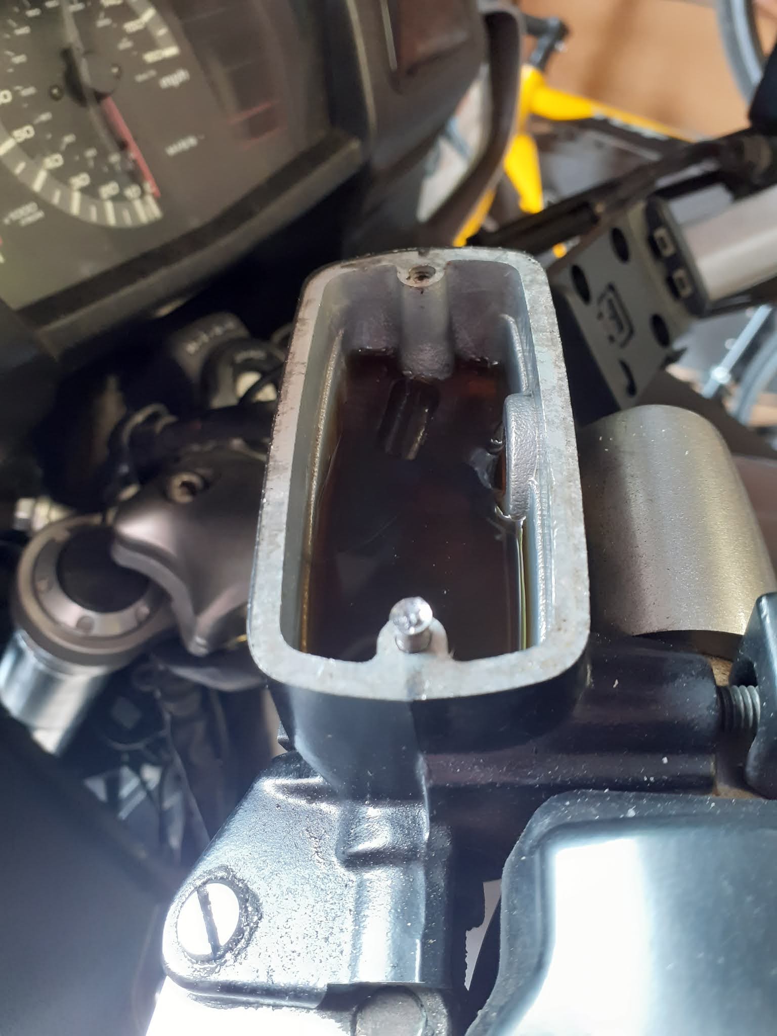
   The bike went through its annual MOT (Ministry of Transport) test for roadworthiness as a pass an with no advisories. Advisories being little jobs that need addressing to bring the bike up to MOT standard but not serious enough to constitute a danger to the safety of the vehicle. The testing bloke commented that the bike was a nice example of the marque and in really good order. That was nice to hear given the light restoration I had given it over the winter. He mentioned the action of the clutch lever in passing. I had noticed the bite of the clutch took a little getting used to. I remembered I had topping up the brake fuild in the reservior as a job to do. The fluid was just above the minimum marker. The screws in the reservoir cap were really tight so I put it to the bottom the list as the clutch was working just fine. Now I thought I would do that top up job.

I first got the screwdriver out again and tried the screws. Nothing moved. I did my usual trick of soaking the screws in 3in1 oil over a few days and tried the screws again. I only managed the round them off. I got the thread extarctor kit out. The kit is a series of what look tapered screws but with a left hand thread. The tool is screwed in the rounded hole which was the head of the set screw and turned. The thread bites and is supposed to release the screw....nope, the hole just got bigger. I got the electric drill out and found a drill bit a shade smaller than the head of the screw.


I very carefully drilled out the head of the screw to leave just the thread portion of the screw in position. I had to be very careful. The reservior cap and body the body of the master cylinder is made from a magnesium alloy which is much softer than the steel of the set screw. One slip could damage the cap or body. That would mean a new master cylinder, the sourcing of which would cost time and money. So far this job had cost £3.80. Patience paid off. As soon as the heads where drilled out the reservoir cap came away undamaged. The screw threads were still in the reservoir body. With some tepidation I turned the remainder of the screw with my fingers. The thread turned easily and were removed in seconds to my great relief. I was not happy contemplating stud extraction for the master cylinder body. The fluid in the reservoir look really dirty. I guess it has been in there since the bike was built in the factory. I used a syringe to remove most of it and topped up te reservoir with fresh clutch/brake fluid. The oil seals and space was cleaned and refitted. The reservoir cap was cleaned and checked that the new screws would seat in the cap. There was a lot of corrosion at the base of the set screw as it went into the master cylinder body. That was what was preventing the screw coming out. I put a smear of copper slip grease on the underside of the set screw before refitting it through the cap. The screw seated nicely. So that job was done. Whilst I was about ti replaced the screws in the front brake master cylinder. These screws came out with much effort. The new screws were copper greased and refitted. The work of a few minutes.

Whilst I was dealing with the clutch master I took off the clutch lever and actuating rod. These components were dirty but well oiled. I cleaned up the lever, rod and housing then a liberal dose of LM grease the rod was refitted into the clutch piston and the other end into the clutch lever. The lever was then positioned for the pivot bolt to be relocated and the securing nut fitted. The lever action feels a good deal smoother.

Three jobs ticked off the list and one added......change clutch fluid. 

Sunday, 10 May 2020

Power part 2

   This post should where has the power gone! When the fairing was refitted, the USBs were connected up. It was a real treat to see them work first time. The USB with voltmeter was particularl good. I turned the bike off and left it until the next time I was able to do some more fettling.

 
At the next visit I turned the ignition to be greeted with the sound of relays clicking and dull dashboard lights. I looked at he voltmeter and it was showing 9 volts. It occured to me that the LEDs onthe USBs had run down the battery over a week. I connected the batery charger and went away to think about the situation. I decided to test the hypothosis. Once the battery was showing recharged I pulled the fused for the USBs and sat back to see what would happen. I went back to the bile a few days later, using a multimeter i tested the voltage of the battery. It had dropped again but not quite as far. The new fuse box has LEDs to show when a fuse has blown. It was with some frustration I disconnected the power feed from the battery to the fuse board. The charger was reconnected. The voltage was checked after a few days. No loss of power and the bike would start on the button. Now what?


   It took a few minutes for the issue to percolate in my bonce but the action was clear. I need to switch off the fuse booard when it is not needed. I could wire a switch into the heavy duty power feed so the solution had to involve and relay. I had a suitable relay in the tool box. I changed the post terminal tag connect to the live feed wire from the battery to a spade connector. That connector went on the replay. I made a jump wire with a post connector one end of the 27amp wire and a spade on the other end. Now I had a relay in between the battery and the fuse board. The wiring was checked with the multimeter. there was no current getting the fuse board. I put two spade conectors on the wires of a twin cable and conected them to the switch side of the relay. I stripped the wires at the other end of the cable and touched them off the battery. The repaly and fuse board reacted when power was applied to the switch wires. So that works.

   The relay needs somewhere to live. Luckily the battery box has a handy size void at the rear of the box which forms part of the rear inner mudguard. It was a simple job to drill a hole through the mudguard, its plastic, and use a plastic number plate nut and bolt to secure the relay to the mudguard. I had measured the jump wire to allow the relay to be fitted in the void.  

    The only problem is that I now have to decide where the switch is to be fitted and what type of switch to use. Then I have to buy it. Then fit it.

   I had a suspicion the battery would not be capable of sustaining so many warning lights. the battery is tiny compared with that of a BMW which is essentially a small car battery rather than a standard bike battery on the pan. The difference is clear but now I have resolved the issue.    

Cleaning

   Despite washing, polish and painting of the running gear the bodywork and wheels still looked dull. They had been washed several times but it does not shine. I set to washing the wheel with Gunk, an engine degreaser Click HERE for website thiinking that would do the job. Things got serious when I got the toothbrush out. The Gunk was loosening the dirt but it need sone scrubing to lift the dirt off the wheels. Cast wheels with twin discs are fiddlily to clean. There are lots of nooks and crannies. Forty minutes of scrubbing had made a difference to the front wheel. It looked much better. The back wheel is not so difficult to get at so gunking and scrubing did not take so long or was as difficult. There is still some skin on my knuckles when I was finished. Washing off the Gunk with hot soapy water revealed some shiny wheels.

   I decided to try the gunk on the bodywork. There was quite alot of accumulated tar on the lower half of the fairing. I tried brushing Gunk on which had little effect. I then put sone gunk on the rag on gently rubbed the area. I was pleased with the results on two fronts; 1,the paint did not come off and B the muck did come off. The Gunk dissolved the tar and cut through the road dirty. With this discovery I went all over the body work with gunk on a rag. More hot soapy water the rinse off the Gunk and the job was done. The bike fairly sparkled. It made a nice job of th ethe crud that had built up on the headlights lens.

   The bike dried quickly in the sun so I thought "make hay". I found some T-Cut (click HERE for website) in the garage cupboard. I carefully applied the T-cut. If you are not careful you can cut right through the paint. I let the T-Cut dry and buffed it off. Again there was dirt ont he rag and the paint shone a little more. Whilst we are at it I might as well go mad I thought. I rummaged in the garage cupboard for Turtle wax polish (click HERE for website) . This was applied to the panels and allowed to dry then was buffed off. For the first time the bike shone. Metallic grey is not that easy it make shine been there was a clear difference between starting and finishing.

   The downside is that the smell of  Gunk lingers so we had a smelly garage for several days. My hands were filthy and there was buckets of water about so there are no photos of the cleaning session.

Exhaust system

   I had tackled the headers whilst I was dealing with the clean and paint of the engine after the service, Click HERE to read about that. The silencers had both been taken off at an early stage and parked up at the back of the garage. They where not in bad shape. a scratch here and there and just a bit grubby. They where quite clean because you can get at them easily so general cleaning is not a problem.

It had occured to me that once I broke the seals on the exhausts they would probably not be reusuable. The OEM exhaust clamps where it bit tired. I figured I would probably break them as I removed them and so I got a set of exhaust gaskets and stainless steel clamps.

   It took a bit of fiddling to get the graphite gaskets off the pipes. As expected they were destroyed in the process. I used wire wool to clean up the are where the gasket had been.

   The jobs was simply enough. Wash the the dirt off. Use Gunk degreaser for the heavy stuff, rinse with hot water. They where better but to finish them off toothbrush and Autosol (click HERE for website). The Autosol and elbow grease did a good of removing the barked on grime. The photo doe snot begin to do the job justice.

  The silencers were returned to their corner of the garage until they were ready to refit to the bike. Fitting them to the bike was a doddle. The gaskets slipped on snugly, I was very careful with them. I remembered to slip the clamps over the pipe beforejoining up the silencer to the header collector pipe. The mounting bolts went strightin, with a dab of copper slip to help get them out if they ever come off again. The clamps were nipped up. Lter when the bike was run there were no leaks fro the exhaust.


POWER !!

   These big touring machines, like the Pan, have lots of options for accessories. In my case I have a bunch of options on my wish list.
  • USB connection to charge my phone seems a no brainer. If we are having one then lets have one in each fairing pocket. 
  • A power connection for the Sat Nav (I don't yet have)
  • An accessory power port
  • Heated seats are a possiblilty 
   There is a connection in the left hand fairing for accessory power. You have to but a wiring sub harness called a quartet harness. Unfortunately I do not want the accessories designed by the harness. I had a fish round tinterweb and came up with a small fuse panel. This is a fancy one as it has a LEDs which light up when the fuse fails.

   It took quite sometime to work out where the fused board would fit. After much trial and error I found the board would fit neatly in the tail piece. There is even a rubber strap to secure the unit. The strap is really for the Ignition Control Unit (ICU) which the Fused board sits on.

   I ran a 25amp rated twin wire cable from the battery to the fuse board. I crimped round post connectors to fit on the battery terminals. From the fuse individual twin wire cables were run to the back each of the fairing pockets. There they connected with USB sockets. The cables were neatly run and tied down.

Click HERE to read about fitting the USB sockets.
Click HERE to read about connectinghte wiring using new plugs

   It was not a complicated job once the thinking part of the design was done. Routing the connection around the fuse board is not as neat as I would like but then the fuse board is dsigned for a boat not a bike.